Overview
The goal of this project was to implement an Inverse Kinematics system into Godot using GDExtension that allowed for various bone lengths, number of bones, and number of IK chains. I also had the goal of implementing rotational constraints for each bone joint, but found many difficulties with the implementation. Despite that, I will still cover the different approaches I used as well as the theoretical implementation.
So, first of all, what is Inverse Kinematics? Inverse Kinematics or IK is a way of animating a set of bones to have realistic placement and orientation given some target position. This is really useful for the animation of limbs like hands and feet since it is much easier to give limbs a target position rather than define the rotations of each joint in a chain of bones.
My implementation uses FABRIK, a method defined in the paper FABRIK: A fast, iterative solver for the Inverse Kinematics problem by Andreas Aristidou & Joan Lasenby[1]. Below is the showcase video and following that is a walkthrough of my process and implementation. Here is the Github link for the project.
Video Showcase
Process
To begin, we need an understanding of FABRIK, the method I used for my implementation of IK. FABRIK stands for Forward And Backward Reaching Inverse Kinematics. It is actually a pretty simple method and the name gives us a big hint on how the method works. Namely, there is a forward-reaching and backward-reaching stage, both of which have similar steps.
Firstly, we need a defined chain of bones and joints for a model. I did this with some simple models made both in Godot and Blender, but normally bones would be defined by an animation rigger or modeler. For the sake of explanation, we consider a chain of bones with only four joints.
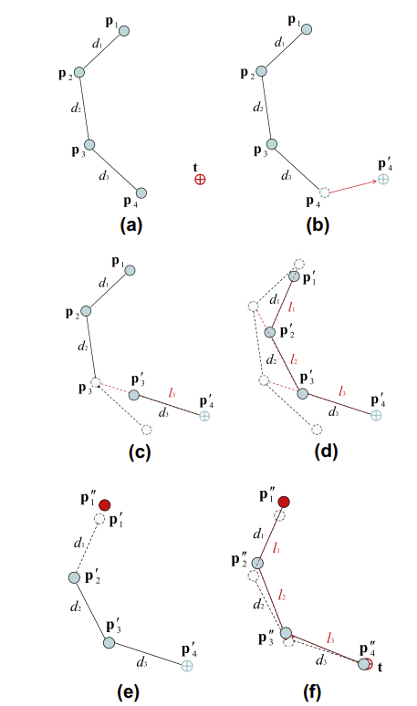
"Bones define how sections of a model will move relative to the changes in the bone orientation and positions, making moving model limbs easier since we don't have to move every joint individually." - FABRIK
The forward-reaching stage is fairly straight-forward, with only two major steps: First moving the end effector (the end joint of the bone chain) to the target position; And second, adjusting previous joints, putting them back at the appropriate distance from the bone before it.
The backward-reaching stage is just as simple, with the process just being performed in reverse. First, the first joint is placed back at the initial position before performing IK. Then, the joints are adjusted in the same way, conserving the distances between bone joints.
Lastly, both stages are performed multiple times until the end effector is within some threshold of the target or an iteration maximum is reached. That's the general idea, however, more specifically, before we begin performing FABRIK, we first check to see if the target is even within range. If it is, then perform FABRIK, otherwise, we have the bones stretch towards the target (which doesn't require the iterative approach above).
Godot Implementation
Now, understanding the method, we can discuss my implementation in GDExtension. I initially planned to incorporate IK changes into Godot using the existing scene-tree hierarchy for transforms, but found that the result was fairly buggy. When I modified the transform data, it would not have the expected result. I think this was due to the scene-tree hierarchy enforcing transform updates to children nodes after the positions were already in the correct spot.
To fix this, my system works outside of the Godot scene-tree, querying the position of some list of Node3Ds (representing the joints), performing FABRIK, then updating the global positions and orientations of the Node3Ds when finished. Specifically, this was implemented using a class called InverseKinematicChain, which derived from the Godot Node class. The class can be configured with an input set of Node3Ds which become the joint positions for the bones. The initial distances between the nodes are the initial distances between the joints and are kept constant.
With this, IK works, but only assuming that the IK chain doesn't move. If the chain were attached to some larger model, the chain would ignore the scene-tree hierarchy of transforms. To fix this, I simply put a marker node at the location of the chain's starting position and update the first joint's position to be placed at this node before each IK calculation.
With that fixed, unconstrained IK finally works completely with arbitrary size and model hierarchies. To add in some more realistic movement, I have an IK controller class, which has some IK chains that it animates based on the movement of the player, extrapolating the speed of the movement of the player to predict joint placement. Also, I added a resting position to which the legs will try to return to if the movement has been still for some amount of time.
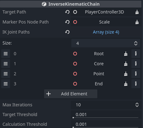
All these properties can be edited within the editor for ease of use, the appearance of which is shown here.
Rotational Constraints
I will first walkthrough an explanation for rotational constraints as it is discussed in the paper. It is a bit more complicated than the unconstrained method, but luckily doesn't need to concern itself with jacobian matrices that typical rotational constraints for IK need to worry about.
The basic idea is that there are rotational constraints on each joint which constrains itself in only two major axes (relative to the bone), the vertical and horizontal.There is also the axis that the bone can spin on, but that axis has no impact on the bone length and thus does not impact the IK solver.
The figure to below showcases how this is done. For the first bone, there are no constraints, so p4 and p3 are moved the same as before. However, now p2 needs to be checked for constraints, thus we draw a line L from the previous bone direction (p3 - p4) and position (p4), then center a cone on the line. This cone is made by the rotational constraints of p2, named θ1, θ2, θ3, and θ4, and the height of the cone is determined by the projection of p2 onto the line L, named O. The figure (figure 4 in the paper) shows how this cone is constructed visually.
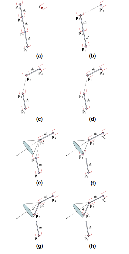
The cone acts to constrain the range of motion for the joint p2, so we first need to check if the joint is outside the range of motion. If it isn't, then there is no reason to perform rotational constraints. In the example, p2 lies outside the range of motion, so it is projected onto the cone, then treated as normal, being constrained to the right position based on the initial distance between itself and p3.
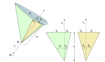
I haven't gone over how to determine if the point is within the range of motion or how to project the point onto the cone if it is. The basic idea is that the point is transformed to the space with O as the origin, then the equation of elipse that makes up the quadrant the point is within is solved for with the point's x,y values. If the value is 1, then the point is outside the range of motion.
For determining the projection onto the cone, the paper solves the eclipse equation and line equation (from the origin to the point). This is done by using the Newton-Raphson method reference from another paper (Sung Joon Ahn, Wolfgang Rauh, Hans-Jnrgen Warnecke, Least-squares orthogonal distances fitting of circle, sphere, ellipse, hyperbola, and parabola, Pattern Recognition 34, 2001). The method seemed overkill to me, especially since FABRIK is already an approximation, so I came up with two alternatives.
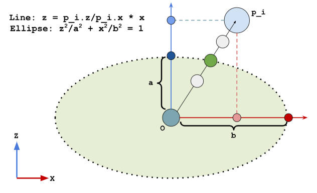
The first alternative method was to pick points along the line, performing essentially a binary search to see if the point was inside or outside the eclipse, progressively getting closer to the edge of the eclipse.
In the figure, the dark red and blue dots are the axis maximums, the light red and blue dots are the projection of the point onto the axes, and the green elispe is the range of motion.
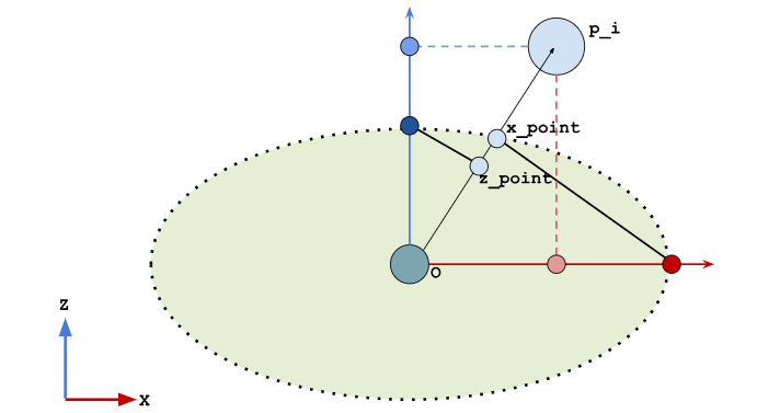
The second approach was to project the axis maximum onto the line from the origin to the target. This was far more approximate but should still work.
In the figure to below, again, the dark red and blue dots are the axis maximums, the light red and blue dots are the projection of the point onto the axes, and the green elispe is the range of motion.
With either approach, I still had problem with rotational constraints working properly. For debugging, I made a visualization that showed the axes of the constrained bones as well as the maximum points for the rotational constraints and the projection of the point onto the axes. Visually, everything seemed to be in order (I used rotational constraints of 45 degrees in each axis). However, the bone chain acted wildly whenever the constraints were enforced.
While working on the project, I thought these problems were coming from solving for the projection onto the cone incorrectly and thus I spent a lot of time trying to fix this problem. However, every approach I took still came up with the same problem. After finishing the project, I believe the problem was actually with the spin of the bones, as the "up" direction of the basis for the bone joint constraints would change every frame (when constrained), thus making the constrainted point position change rapidly. I think I will return to attempt IK in a later project, though I think I might try using a different framework than Godot or use Godot's built-in bones. This way, I might be able to get things to work as expected, as many of my problems in this project came from conflicts between what I expected to happen and how Godot wanted things to work.